Jakub Jansa
Hello, my name is Jakub Jansa. I am from the Czech Republic and this website is basically a place where I put things I work on, think about, or just try out.
I study electrical engineering at SPŠE Ječná (2026), which is nice because it connects quite directly with what I am already interested in — electronics, programming and generally how systems behave.
Most of the time I work with microcontrollers such as ATmega328P, but I also like exploring newer things like RP2350. Not really because one is better than the other, but because comparing them usually reveals how things are actually designed.
I mostly use C and C++, since they stay close to the system.
It is easier to understand what is happening when there is not too much abstraction
in the way (even if sometimes it would be easier).
In general I am interested in how things work internally — how data moves,
how systems are structured, why something behaves the way it does.
That can be anything from small MCU projects to emulation of older systems
like NES, or just random experiments that start with
"what happens if I try this".
A lot of these experiments end up on GitHub, although not everything is polished or even finished. That is kind of the point.
This website works in a similar way — it is not really meant to be a final product. It is more like a working environment where I test ideas (see Tests), break things and sometimes understand them.
I try to keep things simple and understandable. If something feels too complicated, there is a good chance I just don’t understand it properly yet.
I guess this is also why I like the mindset of people like Linus Torvalds or Ken Thompson — focus on what is really happening, not just on using things.
Projects
Some projects start small and stay small. Others grow into something that forces you to actually understand what you are doing. KanderCraft was one of those.
KanderCraft
Overview
KanderCraft is a voxel-based game inspired by Minecraft,
written in C using
raylib
and
stb_perlin.
It evolved from simple rendering into a structured system combining world, rendering and interaction.
World
The world is chunk-based and generated using Perlin noise.
Each chunk stores block data and is saved as .dat.
Engine
Interaction
Raycasting is used for block interaction (place / destroy).
System
Blocks have properties like visibility, solidity and opacity.
Together they form a consistent system.
CHIP-8 Emulator
experimental emulator implementation focused on understanding how simple virtual machines work internally
Useful references: CHIP-8 overview · write a CHIP-8 emulator · test ROMs · technical reference
The goal is not just to make it work, but to understand execution flow, instruction decoding and memory behavior.
Architecture
while (running) {
    opcode = fetch(memory, PC);
    decode(opcode);
    execute(opcode);
    update_timers();
    render_if_needed();
}
The emulator runs in a cycle: fetch → decode → execute. This directly mirrors how real CPUs behave.
Memory & ROM
int load_rom(uint8_t *memory) {
    FILE *f = fopen(ROM_PATH, "rb");
    if (!f) return 1;

    fread(&memory[PROGRAM_START], 1, size, f);
    fclose(f);

    return 0;
}
ROM is loaded into memory starting at 0x200,
which is the standard program entry point in CHIP-8.
Fonts are stored at 0x50, forming a small built-in character set.
CPU Execution
uint16_t opcode = fetch_opcode(cpu);

switch (opcode & 0xF000) {

    case 0x1000:
        cpu->PC = opcode & 0x0FFF;
        break;

    case 0x6000:
        cpu->V[X] = kk;
        break;

    case 0xD000:
        sprite_draw(cpu, Vx, Vy, n);
        break;
}
Instructions are decoded using bit masks. Each opcode represents a small operation on registers or memory.
Registers V0–VF are general-purpose,
with VF often used as a flag register.
Graphics & Drawing
for (y = 0; y < height; y++) {
    byte = memory[I + y];

    for (x = 0; x < 8; x++) {
        pixel = (byte >> (7 - x)) & 1;

        if (pixel) {
            display[x, y] ^= 1;
        }
    }
}
Graphics are monochrome and based on XOR drawing. This allows simple collision detection when pixels are flipped.
Resolution is 64×32, which makes it ideal
for constrained displays.
Input
CHIP-8 uses a hexadecimal keypad (0–F).
Some instructions block execution until a key is pressed, which affects how the main loop is structured.
Direction
The interesting part is not running it on a desktop, but adapting it to limited hardware.
Planned:
• port to AVR platform
• output to OLED display (I2C)
• reduce memory usage
• optimize instruction cycle
Constraints force better understanding.
Analog Video Radio TX/RX
experimental analog RF transmission project — documenting real behavior of signal, noise and physical layer effects.
Log & Notes
This file is basically a buffer for thoughts, experiments and ideas. It will probably contain grammar mistakes — and that is fine.
Not everything is documented, but important moments are.
Test 1 — First RF Experiment (10.2.2026)
Starting point — almost no knowledge about RF or analog circuits. Mostly background in digital systems and microcontrollers.
Goal: verify that signal can be transmitted through air.
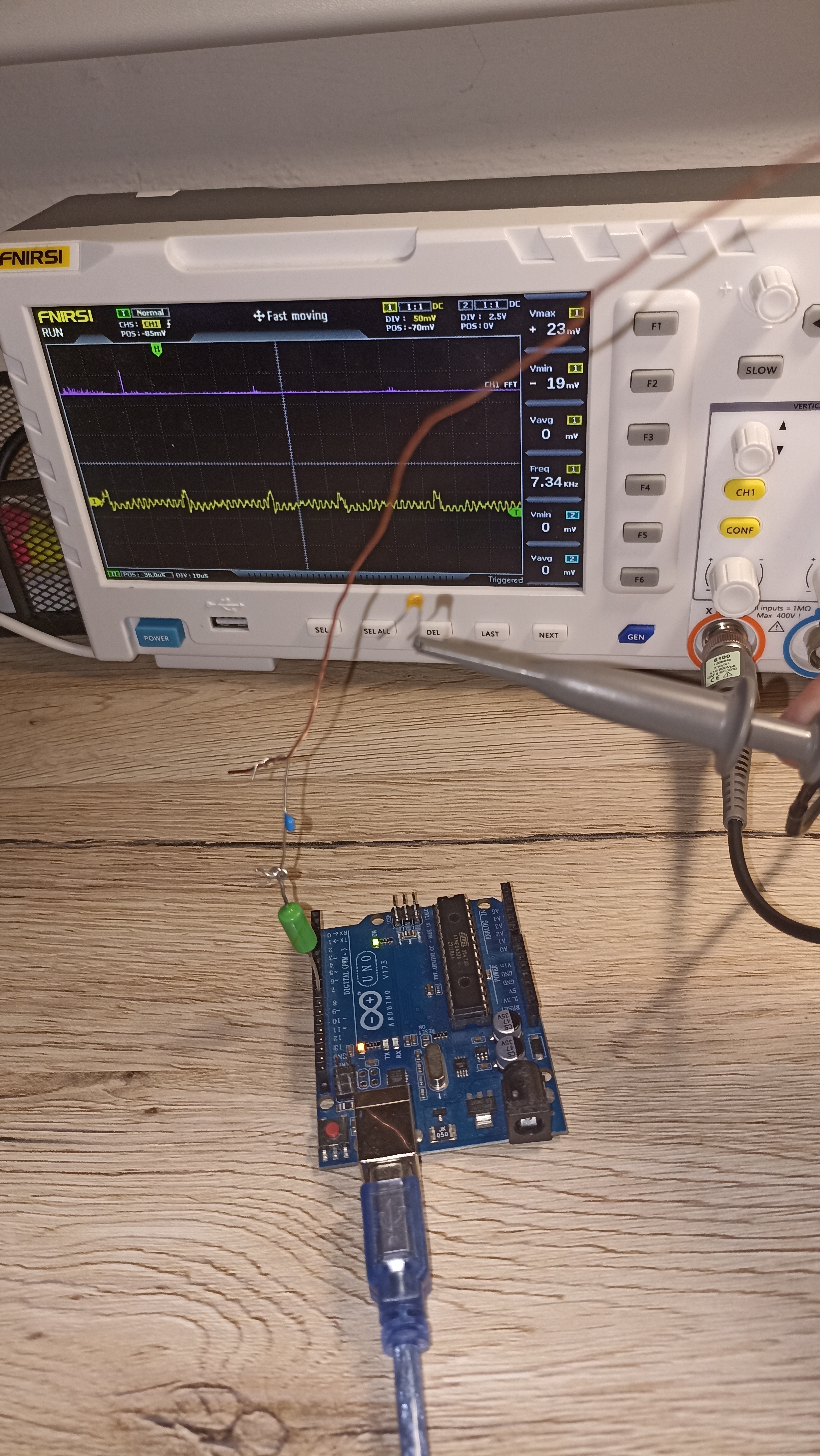
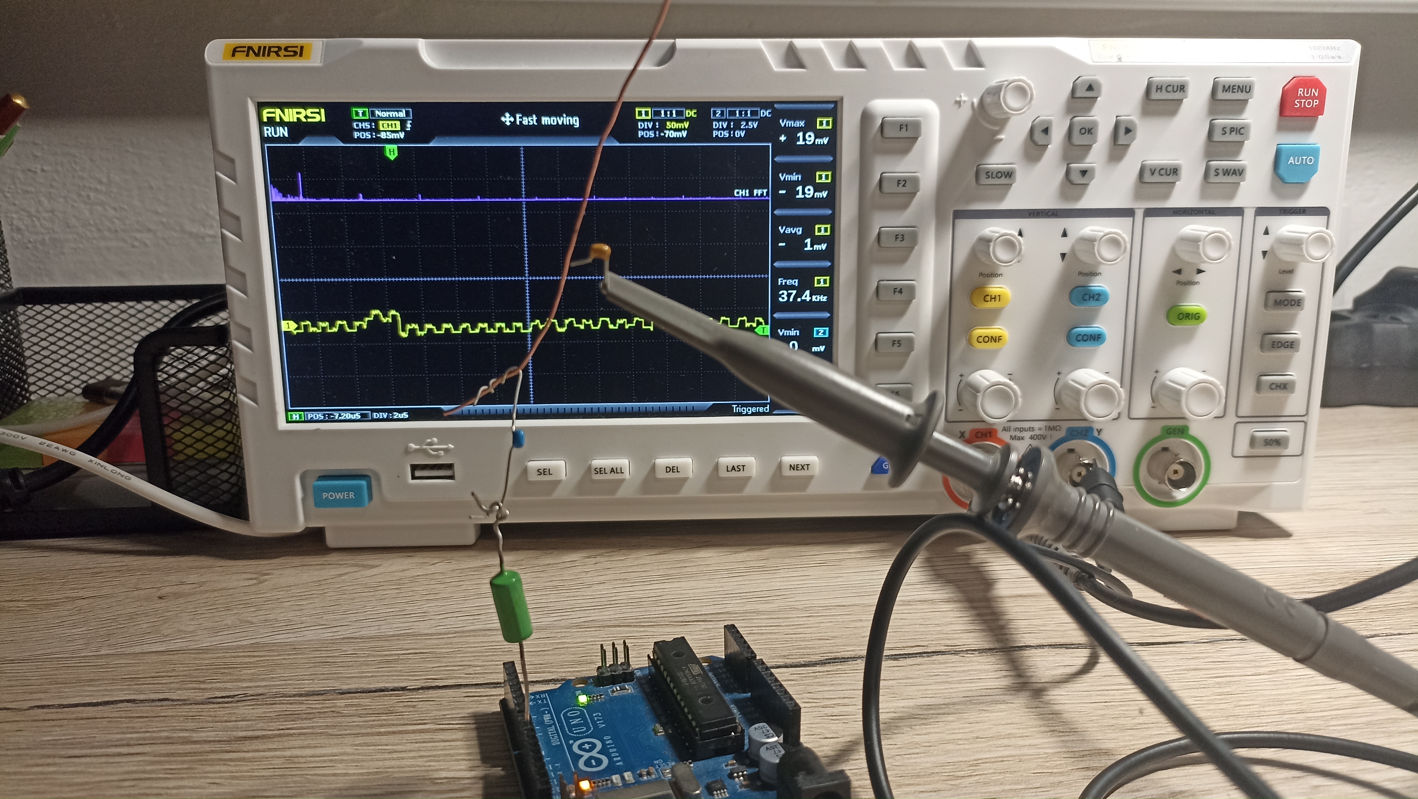
Setup
• Arduino UNO (square wave generator)
• simple R + C antenna
• oscilloscope + probe with capacitor
Timer configured to ~500 kHz using PWM.
Hardware
Result
Signal successfully detected without physical connection.
~20 mV signal observed. Strongest within few centimeters.
Turning off power → signal disappears → confirms real transmission.
Interesting effects
• human body increases antenna size → stronger signal
• Faraday shielding works
• distance directly affects amplitude
Test 2 — LC Resonance
Upgrade from simple antenna → adding LC circuit.
Goal: generate cleaner signal and use resonance.
Design
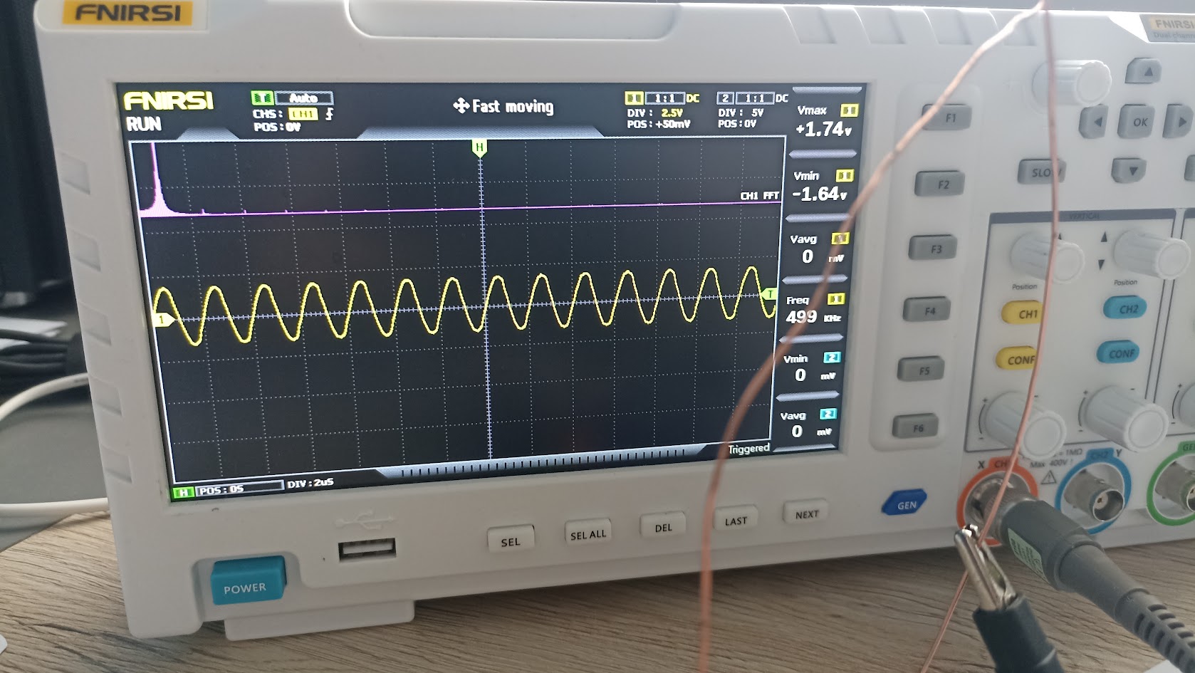
Target frequency: 500 kHz
L ≈ 100 µH
C ≈ 1 nF
Resonant frequency:
f = 1 / (2π√LC)
Coil manually built (adjustable inductance by compression).
Signal & Experiments
Measurements
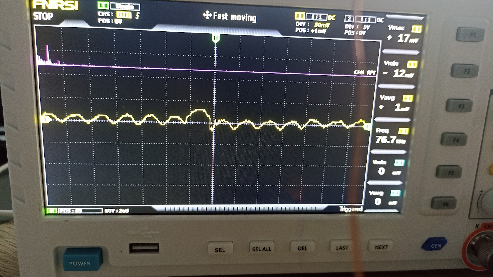
• 100 kHz → unstable
• 300 kHz → better
• 400 kHz → stable (~1.1V)
• 500 kHz → peak (~2V, clean sine)
Outside resonance → signal degrades.
Adding transistor → stronger signal (higher current).
This confirms resonance behavior of the circuit.
Test 3 — Next Step
Planned improvements:
• low-pass filtering
• better signal shaping
• more stable transmission
This is where it starts becoming real system design.
FWKES – Hardware Emulation Platform
Project done with my friend ↗ inunix3
low-level hardware emulation project focused on NES architecture
implemented on RP2350 (Raspberry Pi Pico 2)
This project explores emulation not only as software,
but as a bridge between computer architecture and embedded systems.
Concept
The goal is to emulate a complete system:
• CPU (6502 / R2A03)
• PPU (graphics)
• APU (audio)
• memory + bus
Unlike typical emulators running on desktop OS,
this implementation runs bare-metal directly on MCU.
That means no OS abstraction — full control over:
• timing
• memory
• peripherals
• signal generation
Emulation Model
while (running) {

    cpu_step();        // execute instruction
    ppu_step();        // graphics catch-up
    apu_step();        // audio processing

    sync();            // timing alignment
}
The emulator follows a cycle-based model, where all components
are synchronized on a shared timeline.
A key technique is catch-up mechanism — components
update their state relative to CPU cycles.
CPU Emulation
uint8_t opcode = fetch();

switch(opcode) {

    case 0xA9:
        LDA_immediate();
        break;

    case 0x4C:
        JMP_absolute();
        break;
}
CPU is implemented as an interpreter using classic
fetch → decode → execute cycle.
Each instruction updates:
• registers
• flags
• cycle count
Memory & Bus
uint8_t read(uint16_t addr) {

    if (addr < 0x2000)
        return ram[addr];

    else if (addr < 0x4000)
        return ppu_read(addr);

    else
        return cartridge_read(addr);
}
The bus acts as a dispatcher between components:
• RAM
• ROM
• PPU registers
• I/O
This models real hardware behavior including
memory-mapped I/O and side effects.
Graphics (PPU)
Rendering is based on classic tile-based graphics.
Instead of full framebuffer, the system uses:
• pattern tables (tiles)
• nametables (layout)
• palettes
Rendering approaches:
• frame-based (fast)
• scanline-based (accurate)
• cycle-accurate (experimental)
Hardware Platform
Target platform:
• RP2350 (Pico 2)
• HDMI / DVI output (PIO + DMA)
• SD card (ROM loading)
• PWM audio output
The system is designed as a standalone device, not just a program.
Idea & Motivation
Modern systems hide complexity behind abstraction layers.
This project goes in the opposite direction:
understanding the system from the lowest level.
Emulation here is not just about running games, but about understanding:
• how CPU executes instructions
• how graphics are generated
• how hardware components interact
The result is a compact, real hardware implementation of a complete computer system.
Contact
If you want to reach out — project, idea, or just something interesting — feel free to send a message.
or directly: jansa063@gmail.com